Tuesday, March 5, 2013

How To Write a Project Report?


All engineers need to submit at least one Project Report in four years of engineering. Usually it is done during a training semester but in many prestigious colleges and universities, students are asked to prepare project reports in almost every semester. Writing a report is considered to be a very difficult task, if the student is doing it for the first time. But once you have done it, it becomes an extremely easy and interesting job. We at engineeringcivil.com have received many requests to prepare a format for writing an effective project report for engineering students be it BE, B Tech, M Tech or PHD. First of all you need to understand different levels of Project Reports. If two students one of B Tech and one of M Tech will have to write on same topic, then M Tech students need to do a much more thorough research before preparing a Project Report. But the basic structure remains the same.

Here is the overview of How to write an effective Project Report

1) Title Page
The first page of your report should cover the title of your project along with your name, your guide’s name and your institute’s name along with a line saying “IN PARTIAL FULFILMENT OF THE AWARD OF BACHELOR OF TECHNOLOGY (B.TECH) IN CIVIL ENGINEERING”, (change CIVIL to your engineering branch). Also note if its just a regular report and not a training report you need not write this statement. This is only used when you are submitting your report after a training semester.Here is a sample of Title Page

Project Report
(Project Semester: MONTHS OF YOUR PROJECT WORK)
TITLE OF YOUR PROJECT
Few blanks lines and then add
Submitted by
YOUR NAME
YOUR ROLL NUMBER OR STUDENT ID
Under The Guidance of
YOUR GUIDE NAME
DEPARTMENT OF CIVIL ENGINEERING UNIVERSITY NAME
MONTH AND YEAR OF REPORT SUBMISSION
The formatting should be done with your university logo attached and if you have two or more guides, then they can be left, center and right aligned. Formatting in terms of margins and font sizes will be discussed later.

2) Declaration or Certification
This page is added so that you certify that you have done this project under the guidance of your guide during so and so date. The format looks something like this
I hereby declare that the project work entitled as “TITLE OF YOUR PROJECT” is an authentic record of my own work carried out at “YOUR COLLEGE OR UNIVERSITY NAME” as required for the six months project semester for the award of degree of B.E. (Civil Engineering), under the guidance of ” YOUR GUIDE NAME”, during “DATE AND PERIOD”).
Date: __________
Your Signature: __________
Certified that the above statement made by the student is correct to the best of our knowledge and belief.
YOUR GUIDE SIGNATURE
YOUR GUIDE NAME
HIS OR HER DESIGNATION ( PROF, LECT)
YOUR COLLEGE/UNIVERSITY NAME

3. Acknowledgment
This page is added so that you can add a thank note to all those people who have supported you in your project work. This thank note is not limited to only your guide, you can also add your friends, family members or any other person who has helped you in your project report. Some projects are funded by an organization or government, you also need to thank them for the grant. Sample page can be like this
I would like to express my gratitude to all those who gave me the possibility to complete this project. I want to thank the Department of Civil Engineering and Construction and Maintenance Section of “YOUR UNIVERSITY OR COLLEGE NAME” for giving me such a golden opportunity to commence this project in the first instance. I have furthermore to thank the Professor/ Lecturer ” NAME OF YOUR GUIDE” who encouraged me to go ahead with my project. I am also thankful to the entire Civil Engineering Department “YOUR UNIVERSITY OR COLLEGE NAME” for their stimulating support.
I am deeply indebted to our training in-charge at site “NAME OF YOUR SITE IN-CHARGE” whose help, stimulating suggestions and encouragement helped me in all the time at the training site and also for writing this report. Also I am thankful to Site Engineer “NAME OF SITE ENGINEERS” for helping me understand the process of construction.
My colleagues from the Civil Engineering Department supported me in my project work. I want to thank them for all their help, support, interest and valuable hints. Especially I am obliged to “FRIEND OR COLLEAGUE NAME” who looked closely at the final version of the report for English style and grammar, correcting both and offering suggestions for improvement.
Especially, I would like to give my special thanks to my parents whose patient love enabled me to complete this work. And at last but not the least I would like to thank God for the successful completion of my project.
4. Abstract
This one page should summarize your entire project with special emphasis on keywords, your methodology, tools or software used, your findings and conclusions. Abstract is like the sole of your report and mostly seniors or researchers just read the abstract part to get information about your project.

5. Table of Contents
It should be detailed table of contents and not just the main headings of your Project Work. It should include the segmentation of your report in chapters and should also have sub headings listed along with page numbers. A complete list of tables and figures and list of Symbols and Abbreviations along with proper captions is to be added in the next page after table of contents along with page numbers.
TITLE PAGE………………………………………………………………….. i
DECLARATION…………………………………………………. ..ii
ACKNOWLEDGMENT………………………………………….. iii
ABSTRACTS ……………………………………………………………iv
TABLE OF CONTENT…………………………………………………..v
LIST OF TABLES ……………………………………………………vi
LIST OF FIGURES …………………………………………………. vii
CHAPTER I
1.0 INTRODUCTION………………………………………………..1
1.1 BACKGROUND OF THE STUDY ….…………………………..1
1.2 AIMS AND OBJECTIVES………………………………………4
1.3 SCOPE……………………………………………………………5
1.4 METHODOLOGY……………………………………………….5
CHAPTER II
2.0 LITERATURE REVIEW ……………………………………….6
2.1 HISTORICAL BACKGROUND ………………………………6
2.2.0 NEXT SUBHEADING ……………………………………7
CHAPTER III
3.0 METHODOLOGY ………………………………………………21
3.1 NEXT SUBHEADING …………………………..21
CHAPTER IV
4.0 RESULTS …………………………………………………….. 33
4.1.0 NEXT SUBHEADING……….. 33
CHAPTER V
5.0 CONCLUSION AND RECOMMENDATION …………….. 40
5.1 CONCLUSION ……………………………………………. 40
5.2 RECOMMENDATIONS ………………………………………. 41
CHAPTER VI
6.0 DRAWINGS/PRINT OUT………………………………………. 55
CHAPTER VII
7.0 REFERENCES/ BIBLIOGRAPHY 67
6. Chapters of your report
Till here we have discussed what is the general layout of a project report. After all these pages, your actual project report work details start. This should be divided into chapters and here is a basic overview of how chapters are to be made.

Chapter I – Introduction
The first chapter is the introduction to your work an should cover the importance and concepts used by you in carrying out this project. The basic aim of an introduction is to give an idea of what you have done and how has it been done.

Chapter II – Literature Review
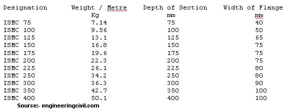
This chapter is basically to tell what work has already been done by other researchers in your project. Any theories, studies, graphs, pictures etc which you are using in your project but have been taken from previous research work should be listed here.

Chapter III – Methodology
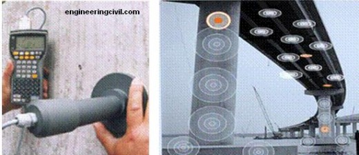
This chapter deals with how you have done your project. To be more precise, here you should list out the methodology adopted by you. You should cover all statistical tools, experiments conducted in lab or site, your methods to collect information etc etc.

Chapter IV – Results
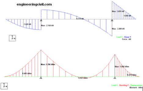
This chapters deals with the results of findings of your report. The data which you had collected by your methodology should be analyzed and the results should be listed in this section. Mostly people use graphical representations to make the results more attractive.

Chapter V – Conclusions and Recommendations
This chapter shows how your report is effective and what you recommend should be done to make the work more effective. After you have found the results of your findings in chapter IV, you just list the main points here so that readers can just find out what your project finally recommends to make the work more efficient and effective. You can also add what should be done in future so as to carry out the research forward.

Chapter VI – Drawings
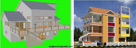
If you have any drawings of the site or any printouts of section details you used in your project, you need to attach them here.

Chapter VII – References/Bibliography
This page lists the references you used while writing this project report. Mostly it is divided into books, Journal, Research paper and Internet websites. One of the biggest mistake people make while writing references is that they just write website reference as www.engineeringcivil.com instead of writing the exact location say (http://www.engineeringcivil.com/how-to-write-a-project-report.html ) of the website from where you have taken the result. When writing references from books and journals you should include Book/Journal Title, Author’s name, Name and Year of publication along with page numbers if possible.

How to format your Project Report
Mostly MS office word is used to prepare reports as its very handy in making changes and also helps in English and grammar check. A basic Project Report consists of 70-100 pages but we don;t have any hard and fast rule on that as pages may vary depending on your Project Topic.

Fonts, Pagination, Spacing and Margins – Mostly we use Times New Roman with font size 12 for the content of our report. But in case of headings and sub headings, font size up to 20 can be used along with bold and underline. Please note subheading should be smaller than headings.
Lowercase Roman numerals i.e. i, ii, iii, and so on should be used for Title, Declaration or Certification, Acknowledgment, Abstract, Table of Contents and then you should use standard number i.e. 1, 2, 3 and so on for your chapters.
Standard spacing of one and a half is used for the report which is reduced to one for Chapter VII – References/Bibliography. A single line space should be given at a start of new paragraph.
Margins should be as follow:-
Top : 25mm
Bottom : 20mm
Left : 20mm
Right : 20mm

Proofreading
Before submitting your report you need to proofread it at least twice to make sure no errors in spellings occur. Basic grammar rules should be followed and you should not use slang language at any point in report. Also avoid the use of abbreviations as far as possible and write complete words.

Finalization of Report
Usually students need to make three copies of training semseter report. But first of all you should take print out of just one copy and get it checked by your guide. Printing should be done on High quality A4 size paper and only on one side. Once the report is checked by you and your guide, get it hard binded and then submit it to the concerned department.

Unit Weight of Materials Used at Construction Site

Following table shows unit weight of materials used at construction site. Please note this is for reference purpose only and may vary from place and type of material.

S.No
Material
Theoretical
Weight in(KG/M³)
Approx Weight at Site in
Remarks
Kg Per
1 Cement 1440 50 Bag
2 Steel 7850 d²/162
d -dia in mm
3 Sand-


Dry 1600 50 to 55 farma 1 farma=1.25cft
River 1840 57 to 63 farma 1 farma=1.25cft
4 Stone(basalt) 2850 to 2960 48 to 52 farma metal 12mm to 20mm
5 Water 1000 1 liter
6 PCC 2240 8.24 to 8.5 Cube mould cube mould size=15x15x15cm
7 RCC 2% Steel 2420


8 Bricks 1600 to 1920 1.9 to 2 no 9x4x2 3/4″

4.8 to 4.9 no 9x6x3 3/4”
9 Brick Masonry 1920


10 Soil(damp) 1760 50 to 55 cft Black cotton
11 Cement concrete block(solid) 1800 18 to 20 cft 30x15x20 cm

10 to 11 no 30x10x20 cm
12 Cement Mortar 2080 57 to 62 cft
13 Lime Mortar 1760 48 to 52 cft
14 Lime 640 30 bag
15 Glass 2530 0.9 to 0.95 sft 4mm tk plain
16 Teak Wood 670 to 830 18 to 20 cft
17 Sal Wood 990 22 to 24 cft
18 Marble mosaic tile
2.8 to 3.2 no 25x25x22mm

4.8 to 5.2 no 30x30x25mm
19 Chequered tile
2.5 to 2.8 no 25x25x22mm
20 Glazed tile15x15cm
0.20 to 0.25 no 5mm tk
21 Marble Stone 2620 5.1 sft 3/4″tk
22 Granite Stone 2460-2800 5.35 sft 3/4″tk
23 Coddappa 2720 6.4 sft 1 1/4″tk
24 A.C.sheet corrugated 16 1.2 sft
25 Bitumen 1040 220 Drum 200liter drum
26 Window frame (simple design)
1.9 to2.1 sft
27 Door Frame


a)3’00×7’0
25 to 27 no section 4″x2 1/2″

b)2’6″x7’0
24 to 26 no section 4″x2 1/2″

What are the Tolerance Limits on Construction Site?

Accuracy of measuring equipment in batching plant.
Cement : + – 2%
Aggregate : + – 3%
Admixture : + – 3%
Water : + – 3%
Mixing time : 2 minutes for one mixing. (Mixing which is being done on site)

Tolerance in Form work
In C/S for columns & Beams deviation is = + 12mm more (or) – 6mm less in size
In footing plan = + 50 mm more (or) – 12 mm less size
In depth = + – 0.05 D (specified thickness).

Tolerance in Reinforcement
For effective depth D < = 200mm = +- 10mm
For effective depth D > 200mm = +- 15mm
For Cover to reinforcement = + 10mm
Maximum freefall of concrete = 1.50 m height.

Tolerance on diameter in length
0-25mm = +- 0.5 %
25-35mm = +- 0.6 %
35-50mm = +- 0.8 %

Tolerance on weight per metre
0-10mm = +- 7%
10-16mm = +- 5%
16 and above = +- 3%

Tolerance for cutting Length
A) When the specified length is not given = + 75mm (or) – 25 mm
B) When the minimum length is specified = + 50 mm (or) – 0 mm

Weight Calculator

Standard conversion factors
INCH = 25.4 MILLIMETRE
FOOT = 0.3048 METRE
YARD = 0.9144 METRE
MILE = 1.6093 KILOMETER
ACRE = 0.4047 HECTARE
POUND = 0.4536 KILOGRAM
DEGREE FARENHEIT X 5/9 – 32 = DEGREE CELSIUS
MILLIMETRE= 0.0394 INCH
METRE = 3.2808FOOT
METRE = 1.0936YARD
1) MILD STEEL (MS)
SHEET
WEIGHT (KGS) = LENGTH (MM) X WIDTH (MM) X 0. 00000785 X THICKNESS
example – The weight of MS Sheet of 1mm thickness and size 1250 MM X 2500 MM shall be
2500MM X 1250 MM X 0.00000785 X 1 = 24.53 KGS/ SHEET
—————————————————
ROLLED STEEL CHANNELS
MS SQUARE
WEIGHT (KGS ) = WIDTH X WIDTH X 0.00000785 X LENGTH.
Example : A Square of size 25mm and length 1 metre then the weight shall be.
25x25X 0.00000785 X 1000mm = 4.90 kgs/metre
MS ROUND
WEIGHT (KGS ) = 3.14 X 0.00000785 X ((diameter / 2)X( diameter / 2)) X LENGTH.
Example : A Round of 20mm diameter and length 1 metre then the weight shall be.
3.14 X 0.00000785 X ((20/2) X ( 20/2)) X 1000 mm = 2.46 kgs / metre
SS ROUND
DIA (mm) X DIA (mm) X 0.00623 = WEIGHT PER METRE
SS / MS Pipe
OD ( mm) – W.Tthick(mm) X W.Thick (mm) X 0.0248 = Weight Per Metre
OD ( mm) – W.Tthick(mm) X W.Thick (mm) X 0.00756 = Weight Per Foot
SS / MS CIRCLE
DIA(mm) X DIA (mm) X THICK(mm) 0.0000063 = Kg Per Piece
SS sheet
Length (Mtr) X Width (Mtr) X Thick(mm) X 8 = Weight Per Piece
Length (ft) X Width (ft) X Thick(inch) X 3 /4 = Weight Per Piece
S.S HEXAGONAL BAR
DIA (mm) X DIA (mm) X 0.00680 = WT. PER Mtr
Dia (mm) X Dia (mm) X 0.002072 = Wt. Per foot.
BRASS SHEET
WEIGHT (KGS) = LENGTH (MM) X BREADTH (MM) X 0. 0000085 X THICKNESS
Example – The weight of brass sheet of thickness 1 mm, length 1220mm and breadth 355mm shall be
1220 X355X 0.0000085 X 1 = 3.68 Kgs/Sheet
COPPER SHEET
WEIGHT (KGS) = LENGTH (MM) X BREADTH (MM) X 0. 0000087 X THICKNESS
Example – The weight of coppper sheet of thickness 1 mm, length 1220mm and breadth 355mm shall be
1220X355 X 0.0000087 X 1 = 3.76 Kgs/Sheet
BRASS / COPPER PIPE
OD (mm) – THICK (mm) X THICK(mm) X 0.0260 = WEIGHT PER METRE
ALUMINUM SHEET
WEIGHT (KGS) = LENGTH (MM) X BREADTH (MM) X 0. 00000026 X THICKNESS
Example – The weight of Aluminum sheet of thickness 1 mm, length 2500mm and breadth 1250 mm shall be
2500x1250X 0.0000026 X 1 = 8.12 Kgs/Sheet
ALUMINIUM PIPE
OD (mm) – THICK(mm) X THICK(mm) X0.0083 = WEIGHT PER METRE

Detailed Units – Convert Units

Following table shows how can we convert various most commonly used units from one unit system to another.
Units to convert
Value
Square foot to Square meter
1 ft² = 0.092903 m²
Foot per second squared  to Meter per second squared
1 ft² = 0. 3048 m²
Cubic foot to  Cubic meter
1 ft³ = 0.028316 m³
Pound per cubic inch to Kilogram per cubic meter
1 lb/in³ = 27679.9 047102 kg/m³
Gallon per minute = Liter per second
1 Gallon per minute = 0.0631 Liter per second
Pound per square inch = Kilopascal
1 Psi (Pound Per Square Inch)  = 6.894757  Kpa (Kilopascal)
Pound force = Newton
1 Pound force = 4.448222 Newton
Pound per Square Foot to Pascal
1 lbf/ft2 = 47.88025 Pascal
Acre foot per day = Cubic meter per second
1 Acre foot per day= 1428 (m3/s)
Acre to square meter
1 acre = 4046.856 m²
Cubic foot per second = Cubic meter per second
1 ft³/s = 0.028316847 m³/s

Measurement Units

Measurement units and standards are different in different countries but to maintain a standard, SI units are mostly used when dealing with projects involving different countries or even different states. Small projects can be done with the locally used unit system but when the project is big, one standard unit system is to be used.
Two most common system used in the United States are
United States Customary System (USCS)
System International (SI)
But the SI unit system is more widely used all over the world. Following is the table which shows how you can convert USCS measurements in SI measurements. ( Just multiply the USCS amount with the corresponding figure given in table below

Convert USCS into SI Units

USCS unit X Factor = SI unit SI symbol
Square foot X 0.0929 = Square meter M2
Cubic foot  X 0.2831 = Cubic meter M3
Pound per square inch X 6.894 = Kilopascal KPa
Pound force X 4.448 =  Newton Nu
Foot pound torque X 1.356 = Newton meter N-m
Kip foot X 1.355 = Kilonewton meter LN-m
Gallon per minute X 0.06309 = Liter per second L/s
Kip per square inch X 6.89 = Megapascal MPa
Clear cover to main reinforcement in
Footings : 50 mm
Raft foundation Top : 50 mm
Raft foundation Bottom/ sides : 75 mm
Strap Beam : 50 mm
Grade Slab : 20 mm
Column : 40 mm (d>12mm) 25 mm (d= 12mm)
Shear Wall : 25 mm
Beams : 25 mm
Slabs : 15 mm or not less than diameter of the bar.
Flat Slab : 20 mm
Staircase : 15 mm
Retaining Wall on Earth : 20/ 25 mm
Water retaining structures : 20 / 30 mm
Sunshade (Chajja) : 25 mm

Hook for stirrups is 9D for one side
No. of stirrups = (clear span/Spanning) + 1
For Cantilever anchorage length for main steel is 69D
“L” for column main rod in footing is minimum of 300mm
Chairs of minimum 12 mm diameter bars should be used.
Minimum diameter of dowel bars should be 12 mm
Lap slices should not be used for bar larger than 36 mm.

In steel reinforcement binding wire required is 8 kg per MT.
Lapping is not allowed for the bars having diameters more than 36 mm.
Minimum number of bars for a square column are 4 and for circular column are 6.
Longitudinal reinforcement should not be less than 0.8% and more than 6% of gross C/S.
Weight of rod per meter length = d2/162 where d is the diameter in mm

All reinforcement shall be free from mill scales, loose rust & coats of paints, oil or any other substances.
Main bars in the slabs shall not be less than 8 mm (HYSD) or 10 mm (Plain bars) and the distributors not less than 8 mm and not more than 1/8 of slab thickness.

In case of spacing of bars
Provide the diameter of the bar, if the diameter of the bar are equal.
Provide the diameter of the larger bar, if the diameter are unequal.
5mm more than the nominal maximum size of the coarse aggregate.

Minimum thickness of slab is 125 mm.
Water absorption should not be more than 15 %.
Dimension tolerance for cubes + – 2 mm.
Compressive strength of Bricks is 3.5 N /mm2
Maximum Free fall of concrete allowed is 1.50 m.
In soil filling as per IS code for every 100 sqm 3 sample for core cutting test should be taken.
Electrical conduits shall not run in column
Earth work excavation for basement above 3 m should be stepped form
Any back filling shall be compacted 95% of dry density at the optimum moisture content and in layers not more than 200mm for filling above structure and 300 mm for no structure
F soling is specified the soling stones shall be laid at 45° to 60° inclination (and not vertical) with interstices filled with sand or moorum.
A set of cube tests shall be carried out for each 30 cum of concrete / each levels of casting / each batch
of cement.
Water cement ratio for different grades of concrete shall not exceed 0.45 for M20 and above and 0.50 For M10 / M15 contractor
For concrete grades M20 and above approved admixture shall be used as per mix design requirements.
Cement shall be stored in dry places on a raised platform about 200mm above floor level and 300mm away from walls. Bags to be stacked not more than 10 bags high in such a manner that it is adequately protected from moisture and contamination.
Samples from fresh concrete shall be taken and at least a set of 6 cubes of 150mm shall be prepared and
cured. 3 Cubes each at 7 days and 28 days shall be tested for compressive strength. The test results
should be submitted to engineer for approval. If results are unsatisfactory necessary action/rectification/remedial measures has to be exercised.
Water used for both mixing and curing shall be clean and free from injurious amounts of oils, acids, alkalies, salts, sugar and organic materials or other substances that may be deleterious to concrete or steel. The ph shall be generally between 6 and 8.

Cement shall be tested for its setting.
1. The initial setting time shall not be less than 30 minutes.
2. The final setting time shall not be more than 10 hours.

Slump IS 456
Lightly reinforced 25 – 75 mm
Heavily reinforced 75 – 100 mm
Trench fill (insitu & Tremie) 100 – 150 mm (For Tremie no need of vibrator)

Curing Days Required
Super Sulphate cement : 7 days
Ordinary Portland cement OPC : 10 days
Minerals and Admixture added cement : 14 days

Cube Samples
1 – 5 M3 : 1 No.
6 – 15 M3 : 2 No’s
16 – 30 M3 : 3 No’s
31 – 50 M3 : 4 No’s
Above 50 M3 : 4 + 1 No of addition sample for each 50 M3.

Computer Diligence For Civil Engineers

Computer Diligence For Civil Engineers

Paper on Computer Diligence For Civil Engineers By
H. J. Sreenivasa (Lecturer) and Nagaraj Sitaram (Professor)
Department of Civil Engineering
School of Engineering and Technology,
Jain University
Jakkasandra Post, Kanakapura Taluk, Ramanagara District-562112


Abstract
Very rapid progress has been achieved in the last few years in the development of general-purpose engineering software that are very efficient in predicting the behavior of engineering structures. General characters desired in computers are speed, accuracy, reliability, versatility and diligence. It can store huge volumes of data and with the aid of many input and output devices data of different forms can be fed in to and taken out.
There are many software packages available in the market exclusively for Civil Engineers. They can be put to use for many uses like design of huge structures, virtual reality, solving equations for optimization of resources tender bidding, earth-work estimation, cost estimation, project management, structural drawing predictive model making and much more. Computers also aid satellite surveying. Data transfer, its interpretation and analysis are all done by computers. It helps making of maps, deciding of highways alignment etc very easy for civil engineers.
The paper deals with many types of software available in the market as tools for Civil Engineers. Among them, the most popular ones are, Auto CIVIL (Civil engineering with Auto CAD), STAAD/Pro (Structural Analysis And Design), 3D Home Architect Deluxe (Dream Home), ANSYS (Structural Analysis).
Computers these days have advanced very much and with the advent of powerful PC’s and Internet, computer has become a immensely useful tool for any one in any field. With the advent of Internet, which is often called as mankind’s greatest invention till date, it has yielded very much for the civil engineers. There are many portals dedicated for civil engineers alone. There are construction site updates in the net. With the arrival of E-commerce, the computers have avoided the hassle of travelling to shops to buy goods like cement, timber etc.
Civil engineers have one of the world’s most important jobs; they build our quality of life with creativity and technical skill. The civil engineers plan, design, construct and operate the facilities essential to modern life, ranging from factories, bridges and highway systems to water treatment plants and energy efficient buildings. The Civil engineers meet the challenges of pollution, traffic congestion, drinking water and energy needs for present and future generation. The paper discusses recent applications of computer in the field of civil engineering and addresses the role of application in transferring information, organizing discussion sessions, conferencing and providing technical advice on line.
With the technological revolution and world’s increasing population great threat is posed on natural resources and global environment. The role of planners becomes important and they need to improve the design skills and construction management techniques in a cost effective manner to make our world a better place to live. Civil engineering is the profession focuses on analysis, design, construction and maintenance of buildings, bridges, transportation systems, water and wastewater systems, and other infrastructure of direct relevance to society’s well-being. More recently, amidst growing awareness on environmental protection, this profession is also entrusted with safe guarding the natural environment around us to promote sustainable development.
In all modern scientific and technological endeavors, computers and software play an increasingly important role. Computers can be used to generate models of fundamental physical processes, which can be solved using numerical methods. In almost all the different aspects of Civil Engineering, it is virtually impossible to escape the application of computer technology. This application of computers in Civil Engineering goes beyond the normal black-box application and requires an engineer to be intelligent and cogent user in order to derive physically sound design and analysis. For example, repetitive and highly involved calculations based on regulatory (Indian standard) code may be needed in the design of multistoried buildings where the tolerance of error is very low; probability modeling may be required in the design of transportation systems, dams and bridges etc. and analysis of new class of problems in civil engineering with project management techniques (PERT/CPM). Very rapid progress has been achieved in the last few years in the development of general-purpose engineering software that are very efficient in predicting the behavior of engineering structures. At the same time transferring information over the internet has started to play an important role in achieving economy in the design process as well as delivering engineering solutions efficiently and promptly making it easier for project managers to meet critical deadlines and obtaining/providing technical advise on line, as well as conferencing and participating in discussion sessions. This is not just about saving time and money. The Web gets creative too.
One of the most widely used software tools in the civil engineering profession is computer-aided design (CAD) software which enables engineers to create 3D models, 2D drawings, and schematics of their designs, satellite surveying, data transfer, structural and fluid behaviour modeling etc. There are number of portals and websites dedicated for civil engineers.

Computers:
Computers data handling and analysis capacity have increased manifolds and used in all branches of engineering for design, optimization and innovation as a tool. The computational capabilities are listed. Information processing and calculation are done by computers at a very high speed. It can execute millions of instruction in a fraction of a second. For example if we want to design a multistoried building, to do the analysis and design, we need a group of engineers working together for weeks together. But in a computer you need a single person with software knowledge and civil engineering background to enter the primary data and the computer will give the results in relatively less time.
Satellite surveying is conducted for map preparation and other projects like highway alignment. Satellite surveying without computers is quite difficult to imagine. Since most of the work is done by the host of computers on board and in ground station. The camera in the satellite is completely controlled by the computer. The photograph taken by satellite will be converted into digital images and sent to earth. At the ground station the receiving end there is a computer, which interprets the data and gives us the real image as taken. The photograph taken can be used as base map and for other purpose like the military use since every thing will be in the proper scale. With out the aid of satellite to survey, it would take many weeks and huge manpower to do the work and that too ends up with many kinds of errors.

Condition Monitoring of Structures:
The bridges and other structures are decaying at very faster rate than expected these structures needs constant monitoring. With suitable hardware support (measurement devices like Smart materials, strain gauge, thermometers, environmental devices etc) and suitable interfacing these structures can be monitored and required alarm can be triggered for safety. The advantage is that it can take into account multi criterias, for example in case if a bridge deflection of the span, sinking of pier, foundation decay, bulking of pier etc. simultaneously and substitute them in the any complex stability equation given and come out with the results in no time. It can monitor and indicate the time when additional prestressing is required in PSC structures.
Probes like deflection gauges can be implanted at different points of a buildings at the time of natural disaster like earthquake, cyclone etc. (you can artificially make for study purpose) These outputs can be fed into a computer and a data base can be made and learnt. The designers can further modify designs economically, to contain these hazards safely in future. In another case a probe can be set upstream in case of a submersible bridge and traffic can be blocked in time.
Monitoring hydraulic structures is a work, which can be done by computer brilliantly. The whole administration with a number of probes in the catchment area can be very well administered. In a project, the regulatory odds can be beaten using software with simulation models. The probability of disputes can be predicted and there by handled effectively. There are risk management softwares, which can predict the amount of risk involved in a project very realistically, with which the management can take decisions effectively.

Health monitoring of a Bridge using smart material sensors
Figure 1 Health monitoring of a Bridge using smart material sensors

Software:
There are many types of software available in the market as tools for Civil Engineers. Among them, the most popular ones are:
• Auto CIVIL (Civil engineering with Auto CAD)
• STAAD/Pro (Structural Analysis And Design)
• 3D Home Architect Deluxe (Dream Home)
• ANSYS ( Structural Analysis)
Auto Civil uses Auto CAD in civil engineering field. The usual areas of its applications are:
a) Digital terrain modeling
b) Roadway design
c) Hydraulics
The digital terrain modeling can be done with Auto contour and Auto DTM in which generation of contour map, point interpolation, 3D residual cut and fill map and even the volume calculations can be done. The roadway design can be done with great ease with Auto roads, which is developed only for this purpose. Similarly Autowater, AutoSewer and Autostorm are the packages, which deal with water supply, sewage, transport and drainage works respectively.

The power tool for Computerized Structural engineering
STAAD.Pro is the most popular structural engineering software product for 3D model generation, analysis and multi-material design. It has an intuitive, user-friendly GUI, visualization tools, powerful analysis and design facilities and seamless integration to several other modeling and design software products. The software is fully compatible with all Windows operating systems(Figure 2). For static or dynamic analysis of bridges, containment structures, embedded structures (tunnels and culverts), pipe racks, steel, concrete, aluminum or timber buildings, transmission towers, stadiums or any other simple or complex structure, STAAD.Pro has been the choice of design professionals around the world for their specific analysis needs.
Shear Force and Bending Moment Diagram from STAAD. Pro
Figure 2. Shear Force and Bending Moment Diagram from STAAD. Pro
3D Home Architect Deluxe creates complete, professional-looking residential floor plans that let you design a remodel, an addition, or even an entire home. 3D Home Architect Deluxe simplifies the task of accurately drawing plans, letting you experiment with possible alternatives and convey your ideas to others. It displays multiple, independent windows, so you can have several views of a single plan open at once (for example, Plan, Cross-Section/Elevation, and Camera views), plus several versions of each view Figure 3 (for example, Camera views from two angles), and even several different plans (to compare designs). The program is designed in such a way that we can create objects or carry out commands, like drawing walls, placing windows, and changing views. Dimension lines locate walls and openings in walls by showing how far one wall is from another, or how far an opening is down a wall. We can create interior and exterior dimension lines. Using landscape we can create our own dream house. Some of the drawing from the 3D Home Architect is given below.
Three dimensional drawing using 3D Home Architect
Figure 3 Three dimensional drawing using 3D Home Architect
The ANSYS program has many finite-element analysis capabilities, ranging from a simple, linear, static analysis to a complex, nonlinear, transient dynamic analysis. ANSYS provides specific procedures to perform analyses for different engineering disciplines.
Analysis in ANSYS
Figure 4. Analysis in ANSYS
The process involves three general tasks Building the Model, Applying Loads and Obtaining the Solution, Reviewing the Results.
Building a finite element model requires more of your time than any other part of the analysis. By specifying a job name, analysis title and by defining the element types, element real constants, material properties we can model the geometry using preprocessor. In the next step, the analysis type and analysis options is defined by applying loads, load step options and initiate the finite element solution. We choose the analysis type based on the loading conditions and the response you wish to calculate. For example, if natural frequencies and mode shapes are to be calculated, you would choose a modal analysis. You can perform the following analysis types in the ANSYS program: static (or steady-state), transient, harmonic, modal, spectrum, buckling, and sub structuring. After the solution has been calculated, the postprocessor is used in ANSYS to review the results. We can obtain contour displays, deformed shapes, and tabular listings to review and interpret the results of the analysis.

Concluding Remarks
The rapid progress that has been achieved in the last few years in the development of general-purpose engineering software as well as the technology of transferring information over the internet has started to play an important role in achieving economy in the design process as well as delivering engineering solutions efficiently and promptly making it easier for project managers to meet critical deadlines and obtaining/providing technical advise on line, as well as conferencing and participating in discussion sessions. This leads to saving of time and money. With recent advances in computer speed, data storage capacity, animation software the Civil engineers are able to optimize the material utilization, construct earthquake resistant energy efficient buildings and develop smart composite materials for future generations.

Structural Design of a Bus Terminal

Abstract
Bus-terminal is an essential component of urban transport facilities which defines the beginning (origin) or end (terminating) of the line for the transportation system. It normally requires a size-able land in a strategic part of an urban area. A well planned or managed bus-terminal will act as catalyst to the social and economic development of the surrounding areas. On the other hand, bus-terminal is an asset to an area as it may act as catalyst to economic and social development of the surrounding areas. However, poorly planned and sited terminal for buses may generate traffic problems as well as deteriorating the quality of life of the affected surroundings. This project focuses mainly the structural design of whole bus terminal. As with engineering and operational aspects of terminal facilities the focus would be on the design to fulfill traffic capacity requirement and operational efficiency to operators and passengers. The proposed far side terminating bas terminal model which located outside city centre may have added advantages such as reducing unnecessary congestion and improving the environment.


Objectives: 
This project have following main objectives:
Conducting research on the existing bus terminal of a city and proposing a new model of bus
terminal according to findings

1. Architectural planning of whole bus-terminal

2. Planning and design of complete bus-terminal
3. Design of a steel garage for bus repairing house and bus storage
4. Design of pavement
5. Material estimation of the whole project
6. Car parking management

Description of the Project
At first i conducted a survey in poorly planned and constructed bus-terminal named “Kodomtoli Bus-terminal” which is located in one of the major city in Bangladesh. After surveying i found the following conditions
1. The ticket counters are situated here and there and sometimes it creates a irritating situation to search expected ticket counter among the passengers.
2. In terms of waiting area, mostly it is not strategic because the plan at bus-terminal is not properly well managed and not suitable for the users and customers.
3. Information on trips and services are not well managed.
4. Public facilities such as toilets, telephone are inadequate.
5. Lack of facilities for staff such as office and control room, storage of personal belongings, rest room, toilets and so on.
6. Unauthorized sale of tickets.
7. Lacking of proper as well as modern repairing house and bus storage garage.
8. Condition of pavement is not good.
9. Poor bus parking management and as a result it creates traffic congestion.
I designed a complete bus-terminal including a terminal building design, a steel garage design by using roof truss system and the rigid pavement design of terminal area and finally gave some feedback to improve car parking management.
Design of a terminal building: I designed a complete terminal building( 150’x150’) with every component like slab, column, beam, septic tank, underground water reservoir, stair, and footing.

Slab design: Slab may be defined as that structural element that is subjected to distribute loads primarily in a plan of slab. R.C.C slabs are provided in different ways depending upon the length and breadth of openings like One-way slab, Two-way slab, Continuous slab etc. I designed three types two-way slab ( i.e. slab continuous with all sides, continuous on two sides and continuous on three sides) with 25’x25’ panel by co-efficient method.

Column design: Columns are the parts of the building which transfer the loads coming over it, along with its weight to the foundation. Two types of columns according to line of action of the loads. They are “Axially loaded columns” and “Eccentrically loaded columns”. Eccentrically loaded columns are subdivided into “Uni-axial column” and “Bi-axial column”. I designed these types of column with details calculation with complete cross-sections. On the other hand, i also designed slender column (length 47’ and diameter 2’) by using ACI moment magnifier method.

Beam design: Beams are the horizontal parts of the structure which transfer the dead and live loads to the vertical members of the structures. There are various types of beam i.e. “Simply supported beam”, “Fixed beam”, “Cantilever beam”, “Continuous beam”. I designed both “Singly reinforced beam” and “Doubly reinforced beam” with shear reinforcement.

Septic tank design: I designed a septic tank ( 34’x12’x8’) for 230 people and assuming production of waste water 90 lpcd with complete calculation and proper cross-section.

Underground water reservoir design: I designed a underground water reservoir (5’x5’x8.5’) for 230 people and assuming water demand 25 lpcd with complete calculation and proper cross-section.

Footing design: I designed column footing assuming fc’= 4 ksi and fy = 60 ksi and bearing capacity of soil 5 ksf with punching and one-way shear check.

Stair design: I designed a stair and landing both assuming thickness of waist 8” with complete calculation and proper cross-section.

Complete steel garage design using roof truss system:
Dimension of proposed steel structure: Considering

Span of truss = 60’
Rise = 12’
Bay = 10’
Steel designation = A36
fy =36 ksi and E = 29×103 ksi


Steps of analysis and design of roof truss system
1. Selection of truss system
2. Estimation of loads
3. Analysis and design of purlins
4. Analysis and design of sagrods
5. Dead load(DL) and wind load(WL) analysis
6. Design of columns
7. Design of column base plate and concrete footing
8. Earthquake load analysis
9. Combination of DL and WL to determine the design bar forces
10. Design of members according to the design bar forces
11. Design of bracing system
12. Design of bolt connections
13. Beam-column joint design
14. Truss-column joint design


Pavement design: Pavement is designed for concrete slabs subjected to patch loading using design charts and joint is also designed.

Software used:
1. STADD.pro for analysis
2. MS office excel for analysis
3. Autocad2007(2D and 3D) for drawing
4. GRASP( Graphical Rapid Analysis Of Structural Programs)
5. Photoshop, Paint, Snipping tool( for figures and pictures)


Significance of this project work:
I think this project work is very helpful for a city to provide a properly planned and organised bus terminal as well as conducting further research regarding bus terminal facilities. In sylhet city, where the “kodomtoli bus terminal” is situated, lack of proper structure, management, facilities are observed. That is why my supervisor Dr. Mushtaq Ahmed, ordered me to work with this poorly built bus terminal and i became able to give the proper plan and structural design of the whole bus terminal after my one year hardship. I also provided some feedback about the bus parking management and total estimated cost. I worked first time with this new as well as unique project work in my department and the dean of “Applied science and Technology”, Head of the department of “Civil and Environmental Engineering(CEE), my supervisor, externals, viva members appreciated me in the day of my project work presentation and inspired me to continue further research on this topic.


References:
Nilson A.H, Design of concrete structure (Twelfth edition-1997), The McGraw-Hill companies inc.
Pytel A. Singer L.S, Strength of Materials(Fourth edition-1987), by Harper & Row Publishers inc.
Gaylord E.H (jr), Gaylord C.N, Stallmeyer J.E, Design of Steel Structures( Third edition-1992), The McGraw-Hill companies inc.
Simplified Design Of Steel Structures(Sixth edition-1990), by Wiley & Sons inc.
Highways-The location, design, construction and maintenance of pavements(Fourth edition), by C.A. O’Flaherty. Butterworth-Heinemann.
Wright H.P, Karen Di, Highway engineering(Seventh edition-2004), by Jhon Wiley & Sons inc.
Rahman SH, Khan A.F. Reinforced Concrete Manual & Building Plan(2nd eidition-1993), by Farah Publishers.
Norris C.H, Wilbur J.B, Utku S.Elementary Structural analysis(Fourth edition-1991), by The McGraw-Hill companies inc.
Shedd T.C, Vawter JA. Theory of Simple Structures(2nd edition-1941), by Jhon Wiley & Sons inc.
Hassoun M.N, Structural Concrete-1988, by Addison-Wesney Publishing Company inc.
Bangladesh National Building Code (BNBC)

http://www.tmc.com.lb/tmc/docs/foundation%20design.pdf
http://en.allexperts.com/q/Civil-engineering-1357/rcc-design.htm
http://en.wikipedia.org
http://www.google.com/images
http://www.streetdirectory.com/asia travel/travel sites/whats nearby/cat/5/bus terminal/
http://www.panynj.gov/bus-terminals/
http://gomexico.about.com/od/mexicocity/gt/df bus stations.htm